کد:
http://www.shudnow.net/2008/04/09/exchange-2007-sp1-scc-using-server-2008-starwind-iscsi-part-3/
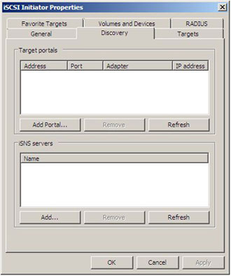
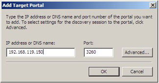
Welcome to Part 3 of this article series. In Part 1, we started off by discussing the goal of this lab. That goal is to showcase Server 2008’s built in iSCSI Initiator software to connect to an iSCSI Target and deploy a Single Copy Cluster (SCC) for Exchange 2007 SP1 Failover Clustering. We first discussed what the lab setup is going to be using VMware Workstation, and then proceeded to the configuration of RocketDivision’s StarWind iSCSI Target software. We then went into Exchange 2007 and did the initial iSCSI Initiator connection to our iSCSI Target.
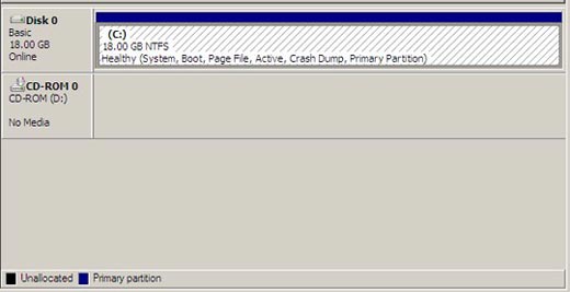
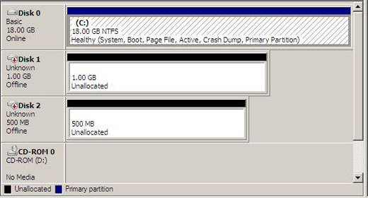
In Part 2, we prepared our Cluster Nodes by installing any prerequisites needed prior to the cluster formation and Exchange 2007 SP1 installation. When that was complete, we continued with our iSCSI configuration by adding our LUNs to the Cluster Nodes, partitioned these LUNs, formatted these LUNs, and ensuring that shared disk storage was working as intended.
In this Part, I will be forming our cluster beginning with Node A followed by Node B. Once our cluster is formed, we will proceed with configuring the cluster to ensure optimal operating for our Exchange server. This consists of cluster network configuration, quorum configuration, etc. Once configuration is completed, we will validate cluster operations. This includes but is not limited to testing failover.
Failover Cluster Installation (NodeA)
Validate a Configuration
All of our prerequisites have been completed. It is finally time to get the cluster up and running. The first step is to go on NodeA while NodeB is shut down (or paused will suffice in VMware). Go to
Start >
Administrative Tools >
Failover Cluster Management.

This will launch the Failover Cluster Management MMC. The section we will be working with the most is Management.
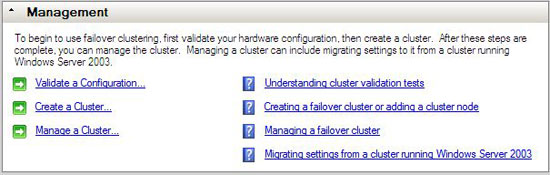
The first thing we will want to do is
Validate a Configuration. This will help ensure that our NodeA has met the prerequisites for cluster formation.
Click Validate a Configuration to proceed and then Click
Next to bypass the
Before you Begin window. Enter the name of our first node,
NodeA and click
Add. Click
Next to
Continue.

You are presented with a list of checks that will occur. If you would like to learn more about these checks, click
More about cluster validation tests in the bottom part of the window. Click
Next to
Continue.

You will begin to see each Inventory item be checked. It will result in a Success, Failure, or Not Applicable. Once this is complete, the
Cluster Validation Report is displayed. If you have any failures, those failures will need to be remedied prior to continuing the cluster formation.
 Create a Cluster
Now that our cluster is validated, we can proceed with the creation of the cluster. Go back to the Failover Cluster Management MMC and then back to the Management section.
Click
Create a Cluster. This will launch a wizard which will assist us in creating our cluster. Click
Next to bypass the
Before you Begin window. Enter the name of our first node,
NodeA and click
Add. Click
Next to
Continue.

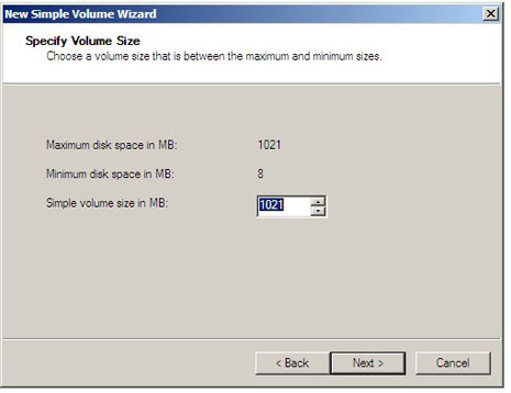
Select an IP Address that you would like to use for administering the cluster. A name for the cluster must also be created. We will use
EXCLUS01 for the cluster name and an IP Address of
192.168.119.220 for the Cluster IP. Click
Next to
Continue.

We are now provided with confirmation of the settings we will use when forming the cluster. Click
Next to
Continue.

Installation will begin and a progress bar will be displayed.

Once this is complete, the
Cluster Summary Report is displayed notifying you whether cluster installation has been successful or unsuccessful. If cluster installation has been unsuccessful, troubleshooting will need to ensue to ensure you can get the cluster installed successfully. Click
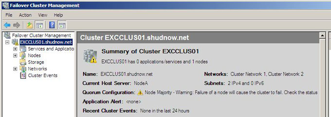
Finish to continue. The Failover Cluster Management MMC re-appears. You will now see that there is an EXCCLUS01 hierarchy with options to modify and manage your cluster. This gives you re-assurance that the cluster installation completed successfully.
[IMG]file:///C:/Users/2623/AppData/Local/Temp/moz-screenshot.jpg[/IMG]
Adding Cluster Storage
Before we bring up the second Node, we need to ensure we add the shared storage to the cluster due to the cluster installation not detecting shared storage and adding it automatically. As stated in this article series, we want the cluster service to have complete control over access to the shared disks. If both nodes are fighting for disk access at the same time, there is a risk of data loss or corruption. This is why we have only had 1 Cluster Node booted at any given time. When in the Failover Cluster Management MMC, Click on
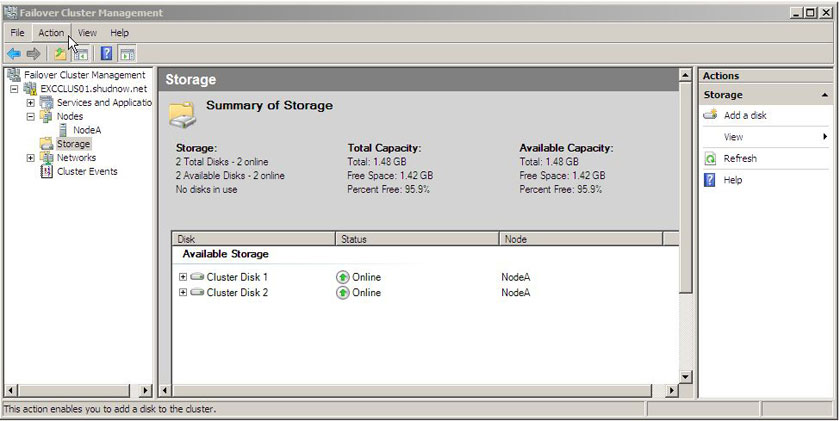
Storage in the hierarchy of EXCLUS01. You will see that no storage exists in the cluster.

In the
Action Pane, Click
Add a disk. Make sure both disks are selected. Click
OK to
Continue.

Cluster NodeA now has full control over both disks.
Select
Cluster Disk 1 and choose
Properties in the
Action Pane.
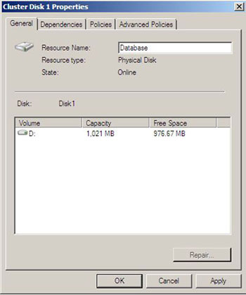
Do the same for Cluster Disk 2 but rename it to Quorum.
Failover Cluster Installation (NodeB)
Validate a Configuration
All of our prerequisites have been completed. It is finally time to get the cluster up and running. The first step is to go on NodeB (It is safe to have NodeA up as the cluster service has control over the disks). Go to
Start >
Administrative Tools >
Failover Cluster Management.
This will launch the Failover Cluster Management MMC. The section we will be working with the most is Management.
The first thing we will want to do is
Validate a Configuration. This will help ensure that our NodeB has met the prerequisites for cluster formation.
Click Validate a Configuration to proceed and then Click
Next to bypass the
Before you Begin window. Enter the name of our first node,
NodeB and click
Add. Click
Next to
Continue.

Select an IP Address that you would like to use for administering the cluster. A name for the cluster must also be created. We will use
EXCLUS01 for the cluster name and an IP Address of
192.168.119.220 for the Cluster IP. Click
Next to
Continue.
You are presented with a list of checks that will occur. If you would like to learn more about these checks, click
More about cluster validation tests in the bottom part of the window. Click
Next to
Continue.
You will begin to see each Inventory item be checked. It will result in a Success, Failure, or Not Applicable. Once this is complete, the
Cluster Validation Report is displayed. If you have any failures, those failures will need to be remedied prior to continuing the cluster formation.
Joining NodeB to Cluster
While on NodeB, open the Failover Cluster Management MMC. Since NodeB is not a part of the cluster, we will see no cluster to manage. Right-Click
Failover Cluster Management >
Manage a Cluster.
Note: Joining NodeB to the cluster will require less information than it did when initially creating the cluster. This is because your 192.168.119.0 network has been chosen to be the network that administers the cluster.

Type in the Cluster Name EXCLUS01. The NetBIOS name or FQDN should both work if name resolution is properly configured in your environment. Click
OK to
Continue.

Right-Click our
EXClus01 Cluster and choose
Add Node…
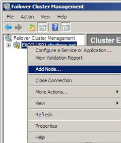
This will launch a wizard which will assist us in joining our existing EXCClus01 cluster. Click
Next to bypass the
Before you Begin window. Enter the name of our second node,
NodeB and click
Add. Click
Next to
Continue.

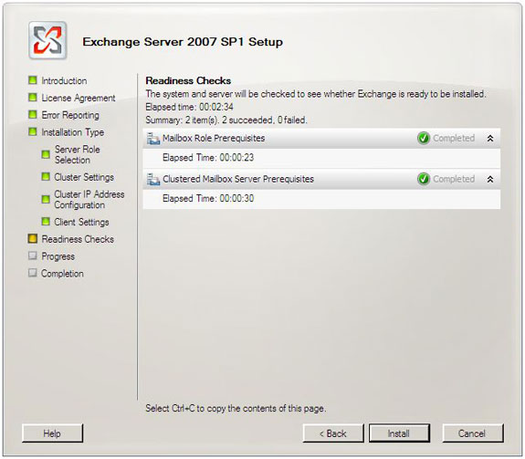
At this point, you will be asked to go through another validation which tests both NodeA and NodeB together. One test that is done is taking storage offline to test storage between the cluster nodes. For example, testing disk failover, testing operating system versions between both nodes, and a slew of other tests to ensure that both nodes will function properly together in a cluster . Since I have shown how the validation tests work twice, I will not include a how-to screenshot on running a third validation test. Click
Next to
Continue once the validation pass succeeds.
We are now ready to add NodeB to our cluster. Click
Next to
Continue.

Installation will begin and a progress bar will be displayed.

Once this is complete, the
Add Node Summary Report is displayed notifying you whether adding NodeB to the cluster has been successful or unsuccessful. If adding the node has been unsuccessful, troubleshooting will need to ensue to ensure you can get NodeB successfully added to the cluster. Click
Finish to continue. The Failover Cluster Management MMC re-appears. You will now see that there is NodeB under the Node section in the EXCClus01 cluster hierarchy. This gives you re-assurance that NodeB was added to cluster successfully.

After adding a second node, your disk witness will automatically be selected. In the case of this lab, our disk witness was set to use the database disk. This will need to be changed.
This will be modified later in the article.
Configuring Cluster Network
NIC Configuration
We will now want to configure the cluster networks. In Server 2003 clustering, we had three options:
Administrators would configure the NICs in one of two different ways depending on the cluster design/needs:
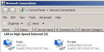
Method 1 (Public/Private)
Public NIC – Public
Private NIC – Private
Method 2 (Mixed/Private)
Public NIC – Mixed
Private NIC – Private
In Method #1, the Public NIC could only be used for client communication and not heartbeat communication while the Private NIC was the only NIC used for heartbeat communication.
In Method #2, the Public NIC and Private NIC were used for hearbeat communication but the Public NIC was the only NIC allowed to accept client communication via the corporate network. In this case, the Private NIC was given a higher priority for cluster communication so the cluster hearbeat would preferrably use the Private NIC. In case of Private NIC failure, you would still be able to use the Public NIC for temporary heartbeat communication. This is my preferred method for reasons of redundancy, and is also the method that is used in Server 2008.
Note: When configuring clustering in Server 2008, you cannot use one NIC as Public and one NIC as Private anymore. You must use one NIC as private and one NIC as mixed (which would be Method 2).
Clustering NIC configuration options are as follows:

When in the Failover Cluster Management MMC, Click on
Networks in the hierarchy of EXCLUS01. You will see that two Networks exist.
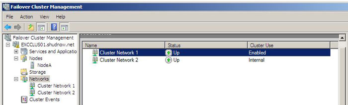
There are three types of Cluster Use:
- Enabled = Mixed
- Internal = Private
- Disabled = Unmanaged
Select
Cluster Network 1 and choose
Properties in the
Action Pane.
We will then want to take a look at the options that are specified on this Cluster Network 1. We see that this is the NIC that belongs to our corporate network that we will want to use for both Client Communications as well as heartbeat communications. As I said earlier, we must configure 1 NIC to be mixed and 1 NIC to be private; this NIC being the public NIC as it belongs to our public 192.168.119.0/24 network.. Selecting both “
Allow the cluster to use this network” and “
Allow clients to connect through this network” equate to mixed mode. After ensuring these settings are correct on your Public NIC,
rename the Cluster Network 1 to something that is more intuitive, such as
Public.

Select
Cluster Network 2 and choose
Properties in the
Action Pane.
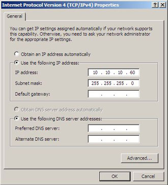
We will then want to take a look at the options that are specified on this Cluster Network 1. We see that this is the NIC that belongs to our private heartbeat network that we will want to use solely for heartbeat communications. As I said earlier, we must configure 1 NIC to be mixed and 1 NIC to be private; this NIC being the private NIC as it belongs to our private 10.10.10.0/24 network. Selecting “
Allow the cluster to use this network” without the option “
Allow clients to connect through this network” equate to private mode. After ensuring these settings are correct on your Public NIC,
rename the Cluster Network 2 to something that is more intuitive, such as
Private.
 Hearbeat Tolerance Configuration
Exchange 2007 also requires we use Cluster.exe to configure tolerance for missed cluster heartbeats. To do this, open a Command Prompt.
We will first want to ensure that each of our Cluster Nodes are currently online. To do this, type the following command in the command prompt:
cluster EXCClus01 Node
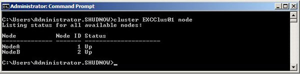
Ensure that the
Status for each node is
Up. If this is successful, run the following two commands on your cluster to configure the heartbeat tolerance:
cluster EXCClus01 /prop SameSubnetThreshold=10
cluster EXCClus01 /prop CrossSubnetThreshold=10
 Configuring Disk Majority Quorum
Earlier in the article, it was stated that once NodeB joined the cluster, the Disk Witness Disk was automatically chosen. Unfortunately, the disk witness went onto the Database disk instead of the Quorum Disk.
To configure the Cluster Quorum Settings, Right-Click
EXClus01 >
More Actions >
Configure Cluster Quorum Settings…

Click
Next to bypass the
Before you Begin window.
We are presented with what type of Quorum we want to use. Ensure that “
Node and Disk Majority (recommended for your current number of nodes” is selected. Click
Next to
Continue.

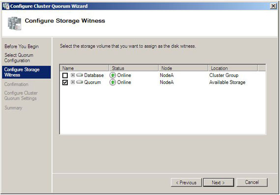
We can now see why the Database was being used for Quorum. There is a checkmark for the Database to be used.
Uncheck this and
place a checkmark next to Quorum. Click
Next to
Continue.
We are now ready to add NodeB to our cluster. Click
Next to
Continue.
Configuration will begin and a progress bar will be displayed.

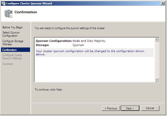
Once this is complete, the
Configure Cluster Quorum Settings Summary Report is displayed notifying you whether configuring the Cluster Quorum has been successful or unsuccessful. If configuring the Cluster Quorum has been unsuccessful, troubleshooting will need to ensue to ensure you can get the Cluster Quorum successfully configured. Click
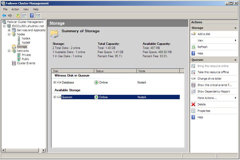
Finish to continue. The Failover Cluster Management MMC re-appears. You will now want to go back into the Storage section and verify the Quorum is configured to use the Quorum disk.

Now that we have everything configured with the cluster, we will want to test failover to make sure the cluster is functioning properly before we attempt to install Exchange. For this, I disabled both NICs on NodeA. I then went onto NodeB, opened the Failover Cluster Management MMC, and looked at the Storage. As you can see, both disks moved to NodeB. I opened the volumes via Windows Explorer and successfully viewed the .txt files I created in previous articles. Success!

I then proceeded to pausing my lab in VMware. I began by pausing NodeB and then verified that storage successfully moved to NodeA; which it did. Success again!
Summary
Well folks, that is all for Part 3 of this article. To recap on what was included in Part 3 of this article series, we first started off recapping what was included in Part 1 and Part 2 of this article and what the goal of this lab is for. It is to showcase Server 2008’s built in iSCSI Initiator software to connect to an iSCSI Target and deploy a Single Copy Cluster (SCC) for Exchange 2007 Failover Clustering. In Part 2, we left off at the final stages of disk preparatation. All of the shared disks were successfully partioned, formatted, and named.
In Part 3, we formed the cluster, beginning with Node A followed by Node B. We then proceeded with configuring the cluster networks, quorum, and validated our failover cluster worked.
For Part 4, I will detail the following:
- Install the Exchange 2007 Active Clustered Mailbox Role in our Single Copy Cluster
- Install the Exchange 2007 Passive Clustered Mailbox Role in our Single Copy Cluster
- Management our Exchange Cluster

 LinkBack URL
 About LinkBacks
.