PART1
Now that Exchange Server 2007 SP1 and Server 2008 is RTM, I thought it would be nice to create an article on how to use Server 2008’s built in iSCSI Initiator software to connect to an ISCSI Target and deploy a Single Copy Cluster (SCC) for Exchange 2007 Failover Clustering. The ISCSI software that will be used is
RocketDivision Starwind. This article is to guide you through the entire process from setting up the ISCSI Target Software, preparing Server 2008 for Exchange 2007, installing Exchange 2007 in a SCC Failover Cluster, and managing your SCC Failover Cluster.
Lab Setup
Guest Virtual Machines
One Server 2008 Enterprise (Standard can be used) RTM/
SP1 x64 Domain Controller which contains the Starwind ISCSI Target software. Exchange 2007 SP1 will be installed with the Hub Transport Server and Client Access Server roles.
Two Server 2008 Enterprise (Enterprise required) RTM/SP1 x64 (x64 required) Member Servers where Exchange 2007 SP1 will be installed with the Mailbox Server role for Failover Clustering
Assumptions
- You have a domain that contains at least one Server 2003 SP2 Domain Controller (DC).
- You have configured the IP settings accordingly for all workstations to be on the same subnet including the public NICs for both Failover Cluster nodes. I have provided the IP scheme of my lab below, but this will vary depending on your needs and VMware configuration.
- You have an existing Exchange 2007 Hub Transport Server as well as a Client Access Server. For the sake of this lab, I will installing the Hub Transport Role as well as the Client Access Server Role on our DC. This is not a recommended practice for production, but for this lab, we will do so to consolidate and conserve resources. This article does not go over the installation or configuration of these roles.
Configuration of VMware Workstation for Failover Cluster Nodes
There is no official VMWare support for Server 2008 at the time of writing this article. The latest version and build is VMWare 6.0.2 build-59824. There is currently “experimental” support which you will see when specifying the Operating System as you create your Virtual Machine. Through my experiences writing Part 1, I did not encounter any real issues related to Windows Server 2008 and VMware Workstation 6.0.2 build-59824.
SCC Failover Clusters using Node Majority with File Share Witness Quorum are supported, but Node Majority with Disk Witness Quorum are preferred. For this lab, we will be using the Node Majority with Disk Witness Quorum. One of the new features of the Disk Witness Quorum, is that it essentially the Quorum Disk from Windows Server 2003 with added benefits. All nodes within the cluster gets a vote, but with the new Disk Witness Quorum model, the Quorum Disk gets a vote as well. So essentially, if your Quorum Disk goes down, your Cluster is still operational.
Processor: 2
Memory: 848MB
Network Type - Public NIC-Network Address Translation (Used so Virtual Machines get an IP Address without taking up IP Addresses at a client’s site while still being granted Internet access through NAT functionality)
Network Type – Private NIC- VMnet9 (Shared with Node2)
Virtual Disk Type – System Volume(C:\)
: VMware SCSI 18GB
Virtual Disk Type – Exchange Database/Logs (D:\):iSCSI 1GB
Virtual Disk Type – Disk Witness Quorum (Q:\):iSCSI500MB
Note: The Virtual Disk for the Exchange Database and Disk Witness Quorum will be created within Windows as part of the ISCSI initiation process and will not be created in the VMware properties. Also, in a production envirnonment, depending on your design, you will most likely expose separate LUNs to separate your Database and Logs due to various reasons such as performance, recoverability, etc. For the purpose of this lab, we will allow for the database and logs to co-exist on the same LUN for reasons of consolidation.
Configuration of VMware Workstation for Domain Controller/Hub Transport Server/Client Access Server/StarWind
Processor: 2
Memory: 1112MB
Network Type -Network Address Translation (Used so Virtual Machines get an IP Address without taking up IP Addresses at a client’s site while still being granted Internet access through NAT functionality)
Virtual Disk Type – System Volume(C:\)
: VMware SCSI 20GB
IP Addressing Scheme (Public Subnet)
IP Address – 192.168.119.x
Subnet Mask – 255.255.255.0
Default Gateway – 192.168.119.2
DNS Server – 192.168.119.150 (IP Address of the Domain Controller/DNS Server)
IP Addressing Scheme (Private Cluster Heartbeat Subnet)
Node A: IP Address – 10.10.10.60
Node B: IP Address – 10.10.10.61
Subnet Mask – 255.255.255.0
Preparation of Cluster Nodes (NodeA and NodeB)
Network Interface Card (NIC) Configuration
First thing we will want to do is configure the IP Configuration of both the Public and Private NIC.
We will want to rename our public NIC connection to Public and our heartbeat NIC connection to Private. To do so, go to
Start >
Right-Click Network >
Properties.

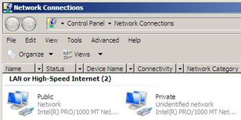
This will bring up the Network and Sharing Center which presents a list of tasks to you on the left-hand side of the Window. Click on Manage Network Connections.

Now you will be presented with the Network Connections window. This is where you can modify the network properties for each NIC in your server. For your public connection, rename your Local Area Connection to Public. Likewise, for your private heartbeat connection, rename your Local Area Connection to Private. After you have done this, it will look something similar to the following:
Part of the assumptions earlier in this article as that you have a properly configured TCP/IP Network where all nodes are properly connected to the TCP/IP Network. Because of this, I will skip the Public TCP/IP Configuration and proceed to configuring the Private Heartbeat NIC. A quick note though – When configuring the Public NIC, I would remove IPv6 but leave both Link-Layer options checked.
Double-Click or
Right-Click >
Properties on the Private NIC to begin configuration.

Uncheck the following:
- Internet Protocol Version 6 (TCP /IPv6)
- Link-Layer Topology Discovery Mapper I/O Driver
- Link-Layer Topology Discovery Responder
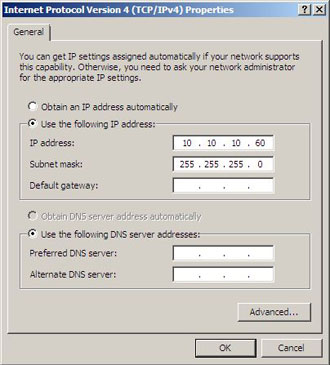
Select Internet-Protocol Version 4 (TCP /IPv4) and press the
Properties button. For NodeA, the only TCP/IP configuration we will need, is the IP Address and Subnet Mask. NodeA’s IP configuration will be 10.10.10.60/24 while NodeB’s IP configuration will be 10.10.10.61/24.
Go into the Advanced NIC configuration settings by clicking the
Advanced button. From there, you will navigate to DNS tab and de-select “Register this connection’s addresses in DNS.”

Select the WINS tab and de-select “Enable LMHOSTS lookup” and configure the NetBIOS setting to “Disable NetBIOS over TCP/IP.”

Once you are done configuring the Advanced settings, press
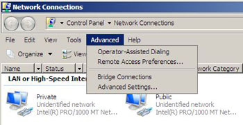
OK three times and you will be back at the Network Connections screen. From here, choose
Advanced and select
Advanced Settings…
.
You will be presented with the Binding Order for your current NICs. Ensure that the Public NIC is on top by selecting Public and pressing the green up arrow key on the right-hand side of the dialog.
 Rename Computer and Join to Active Directory Domain
Windows Server 2008 will automatically assign the computer a random computer name. Because of this, we will change the computer name, join the computer to the Active Directory domain, followed by a reboot. To do this, use the GUI as you normally would in previous versions of Windows, or you can use PowerShell by proceeding with the following steps:
Enter the following lines of code (code thanks to
justaddcode.com) separately in your PowerShell console (PowerShell must first be installed by opening a Command Prompt and typing
ServerManagerCmd -i PowerShell). Once PowerShell is installed, you can open a PowerShell window by navigating to
Start >
All Programs >
Windows PowerShell 1.0 >
Windows PowerShell or by clicking on
Start > Type
PowerShell in search field:
$comp = get-wmiobject Win32_ComputerSystem
$comp.Rename(“NodeA”)
$comp.JoinDomainOrWorkgroup(”Shudnow.net”,”d omainPassword”,”MYDOMAINdomainAdmin”,$null,3 )
Shutdown -r
If you are making these changes on NodeB, ensure that you enter NodeB in the PowerShell code.
Reboot the Cluster Failover Node to complete configuration changes.
Starwind ISCSI Target Configuration
RocketDivision provides an ISCSI Target compatible for Windows Server 2008. This product is called
StarWind. The free version does not provide the capability for more than one node to connect to a target at the same time. I will be using a licensed copy of StarWind to provide you the knowledge needed to fully install a Single Copy Cluster using the Windows Server 2008’s built-in iSCSI initiator.
One thing I want to make you aware of, is that many of us have become accustomed to minimizing utilities to the notification area (system tray) by clicking X. If you do this with StarWind, it will actually close the program instead of minimizing it to the notification area. Also, every time you shut down/reboot, you will have to connect your connection. Your Virtual Disks will still have saved, thankfully. So please be cognizant about this before you continue with your lab.
Once the software is installed on a machine (easy install… no tutorial needed), open StarWind and
Right-Click on your default connection and choose
Connect.

You will then be presented with a password prompt with the default username of test as well as a default password of test. This is configurable in the Connection Properties.

Once your credentials have been entered and OK has been pressed, you will notice that the previously greyed out Connection is now colored. This will allow you to go enter your Registration information for your connection via the Help drop down.

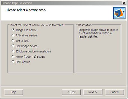
Now that we have a functional connection, we have to add a device to it to allow our cluster nodes to be initiate an iSCSI connection to obtain iSCSI-connected disks. To do this,
Press the
Add Device button on the Toolbar. Select the type of Device you wish to use. For purposes of this lab, we will use an Image File device. Click
Next to
Continue.
Then choose
Create New Image. Click
Next to
Continue.

You will now need to enter the information needed to create the new disk image. The file extension should end with an .img. As you can see from the image below, the image name path might look like something you are not accumstomed to. Click the … button to assist you in selecting the location you would like to create your image. The image name path will automatically be filled in for you. All that will be needed is to fill in the image name.img filename. Finally, specify any additional values you may want such as image size, compression, encryption, etc. Click
Next to
Continue.

When configuring the following screen, you must ensure you Select “
Allow multiple concurrent iSCSI connections (clustering). Click
Next to
Continue.

Choose a
Target Name. This is optional, and if you enter nothing, a default Target Name will be provided. For purposes of this lab, we will specify a Target Name of
Server2008SCC. Click
Next and
Finish to complete the creation process of your disk image.

Once your disk image is created, your StarWind interface should like similar to the following Window.
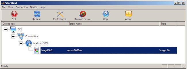
Repeat the steps above to create one additional image file for your Disk Witness Quorum. This disk should be 500MB in size. You will also need to ensure you change the Target Name for the new Disk Image. For this new Disk Witness Quorum, I have named the Target Name as Server2008SCCQuorum. After you are completed, your StarWind interface should look similar to the following Window.
 Exchange 2007 ISCSI Initator Configuration
To begin configuration of the Exchange 2007 Initiator so it can obtain access to the Virtual Disks provided by StarWind, we must first open the iSCSI Initator Console. You will want to do all of the following on both NodeA and NodeB. It is safe to keep both nodes up currently as we won’t actually be exposing any disks to Exchange 2007 until Part 2 of this article series.
Go to
Start >
Control Panel >
Administrative Tools >
iSCSI Initator > Click
Yes to
Continue.

The next option is personal preference. You can choose no if you want to manually configure the firewall. My recommendation would be to
Choose Yes to ensure the firewall rules get properly added. Click
Yes to
Continue.

You will also need to go into the Windows Firewall on the Server which contains StarWind and ensure both a TCP incoming and outgoing Firewall rule is created for port 3260. From my experiences, disabling the Windows Firewall will disable all connectivity with other machines. When I turned off the Windows Firewall, all connectivity to that machine was completely cut off. If anybody knows why this may be, drop me an e-mail. Thanks!
As a side note, one of the things I did do, is log on each server, go into the Windows Firewall properties, and set inbound connections to Allow for the Domain Profile, Private Profile, and Public Profile.
Configuring the Windows Firewall is out of the scope of this article. To learn more about the Windows Firewall, visit the following article:
How to configure the new Windows Server 2008 advanced firewall MMC snap-in
When you have successfully done the above steps, you can now proceed with the iSCSI Initator Configuration.
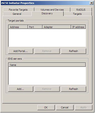
To connect the iSCSI Initator to the iSCSI Target,
Click Add Portal >
Enter IP Configuration for iSCSI Target Server. Click
OK to
Continue.
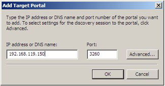
This will expose the targets you created within StarWind as shown in the following image.
 Summary
Well folks, that is all for Part 1 of this article. To recap on what was included in Part 1 of this article series, we first started off discussing what the goal of this lab is for. It is to showcase Server 2008’s built in iSCSI Initiator software to connect to an iSCSI Target and deploy a Single Copy Cluster (SCC) for Exchange 2007 Failover Clustering. We first discussed what the lab setup is going to be using VMware Workstation, and then proceeded to the configuration of RocketDivision’s StarWind iSCSI Target software. We then went into the Exchange 2007 Cluster Nodes (NodeA and NodeB) and proceeded with the initial iSCSI Initiator connection to our iSCSI Target.
For Part 2, I will detail the following:
- Install Exchange Cluster Node Prerequisites prior to Cluster formation and Exchange 2007 SP1 Installation
- Steps required to expose the disks created in Part 1 to both Exchange Cluster Nodes
Elan Shudnow

 LinkBack URL
 About LinkBacks

