کد:
http://blog.augustoalvarez.com.ar/2009/04/21/windows-embedded-standard-2009-step-by-step-deployment-part-ii/
PART-2
After reviewing Post I we’ve set our environment to start
building the images.
The process it’s practically the same that we executed on
XP Embedded (
Post I, Post II and
Post III). And again, as I mentioned before, this deployment is oriented to Embedded images booting on diskless devices, so there will be steps that are not necessary if you are not looking for a remote boot environment with Windows Embedded Standard 2009 images.
Building the Image
1. Get hardware information from your target
This step is done with
Target Analyzer, that is just an .exe file that compiles all of the
hardware necessary information to be included on the image you are building. With the information gathered here, the corresponding
drivers will be added to the image.
Since I’m using virtual machines in the same physical server, I’m going to collect hardware data in the same machine where I’m going to build the target image.
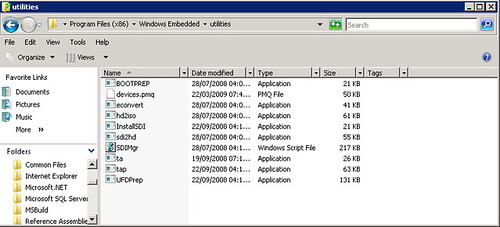
1.1 Open a
cmd and focus on “
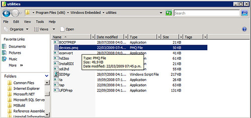
C:\Program Files\Windows Embedded\utilities”.
1.2 Run “
tap.exe”.
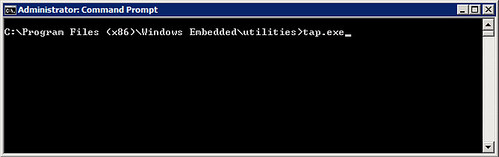
You’ll see that the program recollects information about your devices, and creates a new file on the same folder called “
devices.pmq” containing all that data.
Target analyzer collecting information
 The files devices.pmq contains all the hardware information
 2. Adding the Drivers to the Image
The image builder from the Windows Embedded Standard 2009 suite is still
Target Designer.
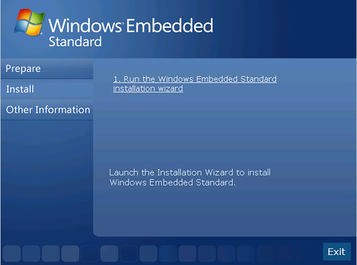
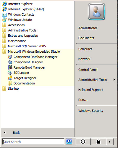
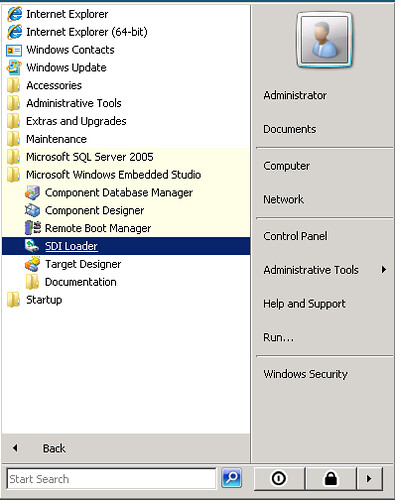
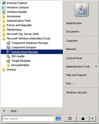
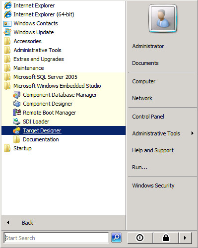
2.1 Open
Target Designer from Windows Embedded Studio.
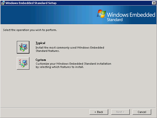
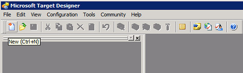
 2.2
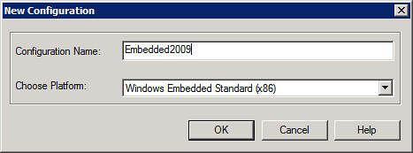
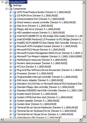
2.2 Select create a
new image and we are going to name it Embedded2009
Now you have to start creating the image from scratch and the first thing we are going to do is
import the hardware information we gathered from Target Analyzer.
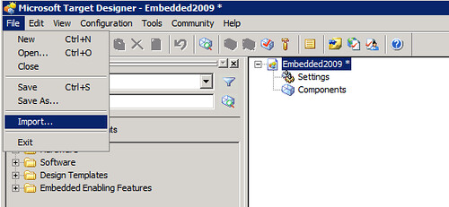
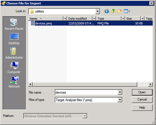
2.3 From “
File” menu select “
Import” and select “
devices.pmq” created recently.
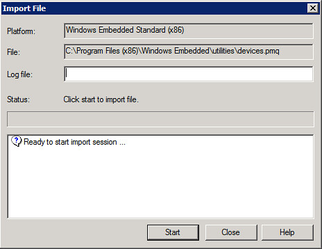
 2.4
2.4 On the “
Import File” window click “
Start” and the importing process will begin.
Once it’s completed, you can check any
warnings generated. In my case, there are several warnings regarding
virtual machines synthetic drivers, those can be ignored for now.
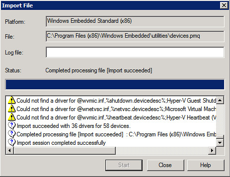
The image now is loaded with a bunch of
hardware components that the image will use.
 3. Using Design Templates and Adding Components
3.1
3. Using Design Templates and Adding Components
3.1 Check on the Target Designer left pane and expand the “Design Templates”.
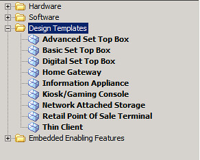
Here you’ll find common templates used when you are creating Embedded images. To find more information about each one, right click on the component and select “
Help”.
I’m going to select the “
Thin Client” component. You can drag and drop the objects to your customized image or right-click and select “
Add”.

This component will generate the necessary requirements that, when the dependency check is run, will add other components included on the database. We’ll see that step later on this post.
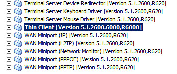
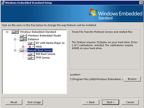
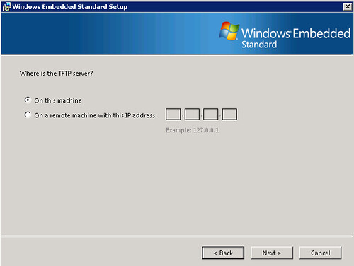
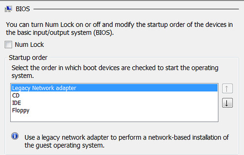
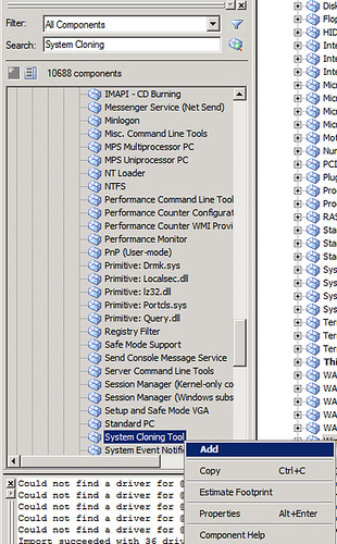
Since we are using a remote boot environment, two special components are needed to achieve it:
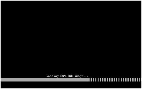
RAM Disk Driver (will allow booting from RAM) and
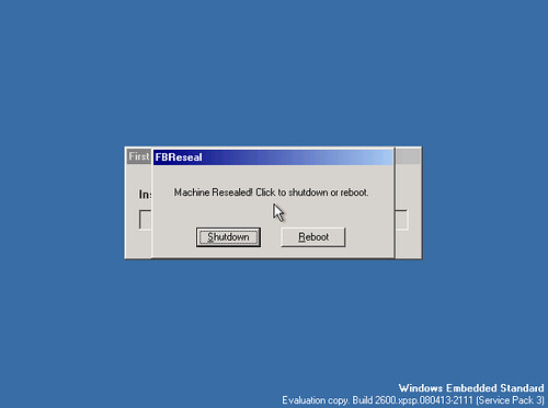
System Cloning Tool (will include a kind of sysprep step, called fbreseal, to make each image unique and avoid cloning SID, computer name, etc each time is deployed).
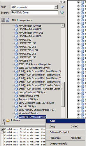
3.2 From the left pane, use the “
Search” box and insert “
RAM Disk Driver”.
3.3 The component is shown. Right-click on it and select “
Add”.
 3.4
3.4 Repeat the step for “
System Cloning Tool” component.
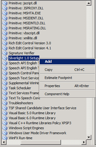
Here’s the chance for you to add any other special component that you want on your image.
.Net Framework 3.5
 Silverlight 1.0
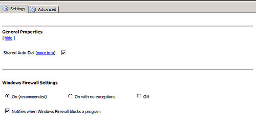
Or even more, you can set some of the components properties at this stage. For example: Windows Firewall.
Access
Windows Firewall component settings

In here you’ll find much more options that the ones shown on XP Embedded
Turn on/off the Firewall by default on your image
 Setting Firewall’s exceptions
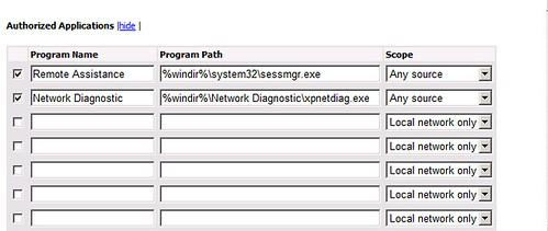
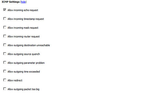 Authorizing applications
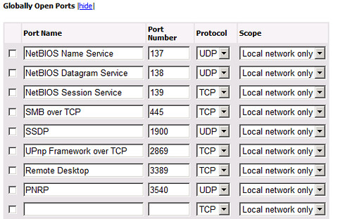
 Opening ports
 4. Checking and Solving Dependencies
The
main step of the building process is checking the dependencies that are created soon as you add a component to your image.
At this point you’ve configured your image with the proper drivers, customized it adding components and setting their properties; now let’s check what dependencies are been set.
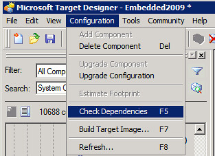
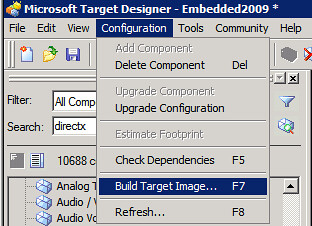
4.1 From “
Configuration” select “
Check Dependencies”.
4.2 In the “
Dependency Check” windows click on “
Start”.
The process will start, it will take a few moments to complete. At the end of the process, you’ll see in the
lower pane window all the messages that need attention before building the image.

Just
double click on each of them to select the proper component to be added and solve the dependency.
Here are some of the common messages that you should see:
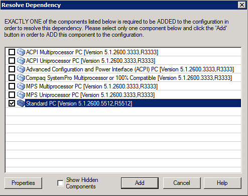
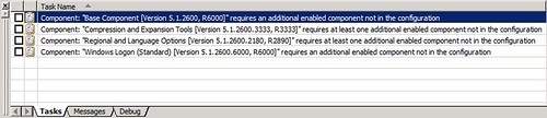 Component: “Base Component”.
 To solve it I’m selecting an standard component “
Standard PC”.
 Component: “Compression and Expansion Tools”.
 Solving it with “
NTFS” component.
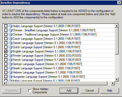
 Component: “Regional and Language Options”.
 “
English Language Support” to resolve.
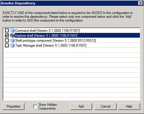
 Component: “Windows Logon”.
 I’m selecting
“Explorer Shell”.
Soon as you click on “
Add” on your last dependency, your image would seem to be ready to the build process, but
not quite.
Since you’ve add new components with the dependency check, it’s
highly recommended that you run the dependency check again for the new ones.
Soon as you finish this new “
Dependency Check” and new and highly important component will appear to be added.
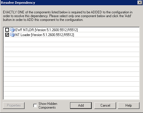
Select your
boot loader. In my case I’m using the default loader for XP and 2003 environments: “
NT Loader”. If you are trying to protect from any change to your boot environment, you can select “
EWF NTLDR” component.
5. Building the Image
Ok, now that we’ve resolved all of the dependencies on our image, we can start building it.
5.1 From “Configuration” select “Build Target Image”.
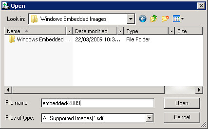
 5.2
5.2 Select the folder where the image will be stored. The default folder is “
C:\Windows Embedded Images”. Click on “
Build”.

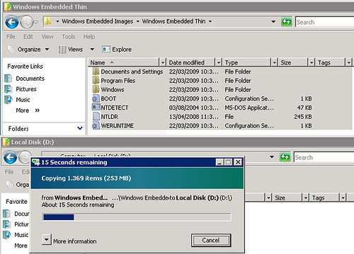
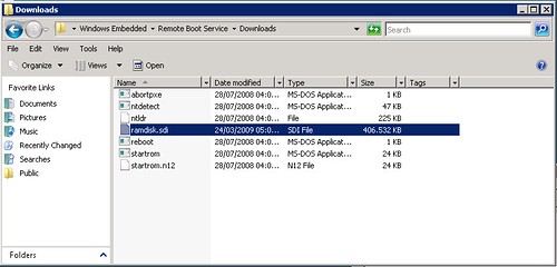
Once the build process is complete, you can check the files and folders created.
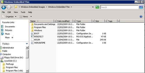
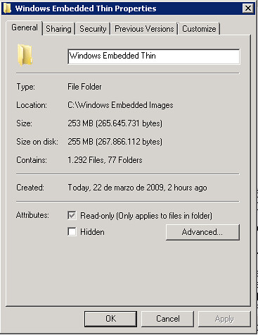
And verify the
image size. In my case is 255mb.
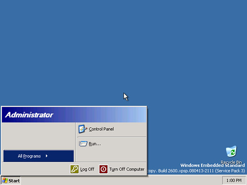
Now the image is completed and ready to be used on any of your targets.
Check the next post about preparing the same image for remote boot on diskless devices

 1سپاس
1سپاس
 LinkBack URL
 About LinkBacks