PART2
Welcome to Part 2 of this article series. In Part 1, we started off by discussing the goal of this lab. That goal is to showcase Server 2008’s built in iSCSI Initiator software to connect to an iSCSI Target and deploy a Single Copy Cluster (SCC) for Exchange 2007 SP1 Failover Clustering. We first discussed what the lab setup is going to be using VMware Workstation, and then proceeded to the configuration of RocketDivision’s StarWind iSCSI Target software. We then went into Exchange 2007 and did the initial iSCSI Initiator connection to our iSCSI Target.
In this Part, I will be preparing our Cluster Nodes by installing any prerequisites needed prior to the cluster formation and Exchange 2007 SP1 installation. When that is complete, we will continue with our iSCSI configuration by adding our LUNs to the Cluster Nodes, partitioning these LUNs, formatting these LUNs, and ensuring that shared disk storage is working as intended.
Prerequisite Installation on Cluster Nodes (NodeA and NodeB)
Downloading XML Files for prerequisite installation
To prepare your server for Exchange installation as well as Cluster installation, there are a number of prerequisites that are needed on each node. The Microsoft Exchange Team presented several XML files which allow you to install the necessary prerequisites for each type of node; whether that may be a standalone Client Access Server, Hub Transport Server, Mailbox Server, Clustered Mailbox Servers, or a Unified Messaging Server.
There is also an XML file for the Typical Installation which includes the Hub Transport Server, Client Access Server, as well as a Mailbox Server Role. Instead of reinventing the wheel, head on over to the blog article that explains these XML files. You can visit that blog entry
here which is based of the Technet article
here. To download these XML files, go to the following URL
here. Save them somewhere on your hard drive (files will be stored on C:\ on both Cluster Nodes) and transfer the following XML files to each Cluster Node:
- Exchange-Base.xml
- Exchange-ClusMBX.xml
Because part of the assumptions are that you have already deployed a Client Access Server as well as a Hub Transport Server, I will not detail the installation process for each of these roles. That can be explained by reading the URLs provided just above.
Installing prerequisites using XML files
The prerequisite installation on both nodes will be identical. Log on to to each cluster node (order is of which cluster node is done first is irrelevant), and open the Command Prompt.

Once in the Command Prompt, we will use the first XML, Exchange-Base.xml, which checks for the following tools and installs if not currently installed:
- RSAT-ADDS – Active Directory Domain Services Remote Management Tools which includes LDIFDE and other Directory Services Tools
- PowerShell
To install these tools using the Command Prompt, type the following command:
ServerManagerCMD -ip C:\Exchange-Base.xml

You will need to ensure the server is rebooted prior to running the Exchange-ClusMBX.xml prerequisite installation. Once the server is back up, proceed to opening the Command Prompt again. Once in the Command Prompt, we will use the second XML, Exchange-ClusMBX.xml, which checks for the following tools and installs if not currently installed:
- Failover Clustering
- Web-Server Role (Internet Information Services 7.0)
- Web-Metabase
- Web-Lgcy-Mgmt-Console
- Web-ISAPI-Ext
- Web-Basic-Auth
- Web-Windows-Auth
To install these tools using the Command Prompt, type the following command:
ServerManagerCMD -ip C:\Exchange-ClusMBX.xml
 Adding LUNs to Cluster Nodes (NodeA and NodeB)
In Part1, we used each cluster node’s iSCSI initator to establish connectivity to our StarWind iSCSI target. This exposed both iSCSI target’s, but the LUNs were not added to either of the Exchange Cluster Nodes. In order to do this,
it is imperative that you only have one Exchange Cluster Node up at any given time until Clustering is installed.
The reason for this is because data could be lost or corrupted if both disks are fighting for disk access at the same time. Once clustering is installed on at least one node, you can bring up the second node as the clustering service will prevent disk control to the node who is not considered the Active Cluster Node. The process of installing Clustering is as follows:
 Setting up shared disks (Node A)
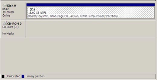
In Part 1, we left off exposing the iSCSI targets to both Cluster Nodes. Now that each node’s iSCSI Initiator can see these targets, let’s begin setting up the shared disk. To proceed, ensure that Node A is turned on and Node B is turned off to avoid lost data and/or corruption. By taking a look at Disk Management (
Start >
Administrative Tools >
Server Manager >
Disk Management), we will see that no shared disks have currently been added to Node A.
Let’s go back to the iSCSI Initiator (
Start >
Administrative Tools >
iSCSI Initiator). Taking a look at the targets, we can see that both are set to Inactive.

For each iSCSI Target, click the “
Log on…” button and place a check mark in the “
Automatically restore this connection when the computer starts.” Click
OK to
Continue.

You will now see that both iSCSI Targets have been Connected (Activated) on Node A.

Go back into Disk Management (
Start >
Administrative Tools >
Server Manager >
Disk Management). We now see that two new shared disks have currently been added to Node A.
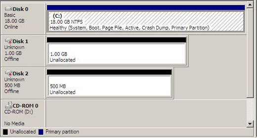
We will want to bring both of these disks Online. You can do this by
Right-Clicking Disk 1 >
Choose Online. Do the same for Disk 2.

Now that both disks are Online. We will want to Initialize these disks. You can do this by
Right-Clicking Disk 1 >
Choose Initialize.

When Initializing Disk1 and Disk 2, choose the following options. Click
OK to
Continue.

Now that we have Initialized both Disk 1 and Disk 2, we will partition both those disks as a Simple Volume and format both volumes as NTFS (I hope nobody still uses FAT!). You can do this by
Right-Clicking the unallocated space for Disk 1 and Disk 1 >
Choose New Simple Volume. This will bring you to the
Welcome to New Simple Volume Wizard. Click
Next to
Continue.
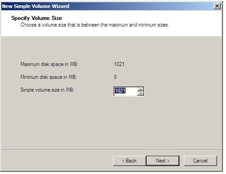
You will now have to specify the Volume Size. In this example, we are specifying the Volume Size for our database volume. You will need to do these steps on the Quorum volume as well. Choose the maximum allocatable space available. Click
Next to
Continue.
Assign the drive letters accordingly. The drive letter D will be for the Database volume and the drive letter Q will be for the Quorum Volume.
Note: You may have to change the drive letter for any CD-ROM, DVD-ROM, or any other volume that may be installed on your system to use the drive letter you want. You can read
here for more information on how to change a drive letter.
For larger servers, you may want to use Volume Mount Points instead of Drive Letters if you would be using more than 26 volumes. Volume mount points are also good for LCR implementations as you can easily switch the target path of the Mount Point if 1 location becomes corrupt. Click
Next to
Continue.

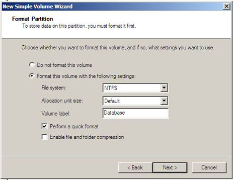
You must finally format the volume. I would give the volume a name, such as Database or Quorum. I would also choose Quick Format. Quick Format prevents a chkdsk being run on the disk prior to a format. Click
Next and then
Finish to
Complete this Process.
When completing this process on both disks, your Disk Management MMC should look similar to the following image.

As an optional but recommended step, I would recommend opening both volumes and creating a .txt file. This will allow you to verify after adding both disks to Node B, that the shared functionality is properly working.
Verifying Disk Configuration (Node B)
We will now need add the fully partioned and formatted disks to Node B. Shut down Node A followed by booting up Node B once Node A has finished shutting down. In the case of this lab, a VMware pause will suffice if you successfully added the clustering option when you created your iSCSI Target within StarWind.
If you forget to choose the Clustering option, you will receive a Connection Error message when attempting to log on to the target. You can do one of two things. The first being is to shut down Node A completely to release the connection to StarWind (not recommended). The second option is to delete the iSCSI target, re-create it within StarWind with the Clustering option enabled. Then go back onto both Nodes, exposing the Target to both nodes, set up the shared disk on Node A and go through the disk initialization, partitioning, and the formatting process explained above. This is recommended since we will need to simulate a Cluster environment in future Parts to this article series.
By taking a look at Disk Management (
Start >
Administrative Tools >
Server Manager >
Disk Management), we will see that no shared disks have currently been added to Node B.
Let’s go back to the iSCSI Initiator (
Start >
Administrative Tools >
iSCSI Initiator). Taking a look at the targets, we can see that both are set to Inactive.
For each iSCSI Target, click the “
Log on…” button and place a check mark in the “
Automatically restore this connection when the computer starts.” Click
OK to
Continue.
You will now see that both iSCSI Targets have been Connected (Activated) on Node B.
Go back into Disk Management (
Start >
Administrative Tools >
Server Manager >
Disk Management). We now see that two new shared disks have currently been added to Node B. Unlike when we did this with Node A, we can see that the disks are formatted and partitioned, but are not online.

Because the disks are not online, we will want to bring both of these disks Online. You can do this by
Right-Clicking Disk 1 >
Choose Online. Do the same for Disk 2.

After the disks have been brought online, they will most likely be using different drive letters than you assigned on Node A. Because of this, you must assign the drive letters to match the same letters you used on Node A. The drive letter D will be for the Database volume and the drive letter Q will be for the Quorum Volume.
Note: You may have to change the drive letter for any CD-ROM, DVD-ROM, or any other volume that may be installed on your system to use the drive letter you want. You can read
here for more information on how to change a drive letter. When completing this process on both disks, your Disk Management MMC should look similar to the following image.
If you performed the optional but recommended step of adding a .txt file to both volumes to ensure shared disk communication was working, now would be the time to open both volumes (both D:\ and Q:\) to see if the .txt files are there. If you do indeed see the .txt file, shared disks is working as intended. If you do not see the .txt file, troubleshooting shared disks will need to ensue.
Summary
Well folks, that is all for Part 2 of this article. To recap on what was included in Part 2 of this article series, we first started off recapping what was included in Part 1 of this article and what the goal of this lab is for. It is to showcase Server 2008’s built in iSCSI Initiator software to connect to an iSCSI Target and deploy a Single Copy Cluster (SCC) for Exchange 2007 Failover Clustering.
In Part 1, we left off at exposing the iSCSI LUNs to our Exchange 2007 Cluster Nodes. In Part 2, we prepared our Cluster Nodes by installing any prerequisites needed prior to the cluster formation and Exchange 2007 SP1 installation. When that was complete, we continued with our iSCSI configuration by adding our LUNs to the Cluster Nodes, partitioned these LUNs, formatted these LUNs, and ensured that shared disk storage was working as intended.
For Part 3, I will detail the following:
- Form the cluster, beginning with the Node A followed by Node B
- Configure the cluster networks
- Configure the cluster quorum
- Validate the failover cluster
Elan Shudnow

 LinkBack URL
 About LinkBacks

